The sign in front of and is opposite for the forward going wave.
True False
In this equation is the total voltage anywhere on the line (at any point z), is the total current anywhere on the line (at any point z), and are the phasors of forward and reflected voltage waves at the load (where z=0), and and are the phasors of forward and reflected current wave at the load (where z=0).These voltages and currents are also phasors and have a constant magnitude and phase in a specific circuit, for example , and . We can get the time-domain expression for the current and voltage on the transmission line by multiplying the phasor of the voltage and current with and taking the real part of it.
If the signs of the and terms are oposite the wave moves in the forward direction. If the signs of and are the same, the wave moves in the direction.
In the next several sections, we will look at how to find the constants , , , , . In order to find the constants, we will introduce the concepts of transmission line impedance , reflection coefficient , input impedance .
We will show next that if the signs of the and have the opposite sign, as in Equation eq:WVfwd1, the wave moves in the forward direction. If the signs of and are the same, as in Equation eq:WVbck1, the wave moves in the direction. In order to see this, we will visualize Equations eq:WVfwd1 and eq:WVbck1 using Matlab code below.
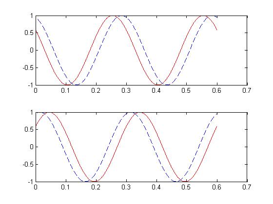
Figure fig:WVfwrdref shows forward and reflected waves on a transmission line. represents the length of the line, and on the y-axis is the magnitude of the voltage. The red line on both graphs is the voltage signal at a time .1 ns. We would obtain Figure fig:WVfwrdref if we had a camera that can take a picture of the voltage, and we took the first picture at .1 ns on the entire transmission line. The blue dotted line on both graphs is the same signal .1 ns later, at time .2 ns. We see that the signal has moved to the right in 1 ns, from the generator to the load. On the bottom graph, we see that at a time .1 ns, the red line represents the reflected signal. The dashed blue line shows the signal at a time .2 ns. We see that the signal has moved to the left, from the load to the generator.
clear all

clc

f = 10^9;

w = 2*pi*f

c=3*10^8;

beta=2*pi*f/c;

lambda=c/f;

t1=0.1*10^(-9)

t2=0.2*10^(-9)

x=0:lambda/20:2*lambda;


y1=sin(w*t1 - beta.*x);

y2=sin(w*t2 - beta.*x);

y3=sin(w*t1 + beta.*x);

y4=sin(w*t2 + beta.*x);


subplot (2,1,1),


    plot(x,y1,’r’),...

            hold on

    plot(x,y2,’--b’),...

    hold off

subplot (2,1,2),


    plot(x,y3,’r’)

        hold on

    plot(x,y4,’--b’)

    hold off
Using Matlab code above, repeat the visualization of signals in the previous section for a lossy transmission line. Assume that Np, and all other variables are the same as in the previous section. How do the voltages compare in the lossy and lossless cases?
The sign in front of and is opposite for the forward going wave.