Any wire, cable, or line that guides energy from one point to another is a transmission line. Whenever we make a circuit on a breadboard, every wire attached forms a transmission line with the ground wire. Whether we see the propagation (transmission line) effects on the line depends on the line length, and the frequency of the signals used. At lower frequencies or short line lengths, we do not see any difference between the signal’s phase at the generator and the load, whereas we do at higher frequencies.
Types of transmission lines
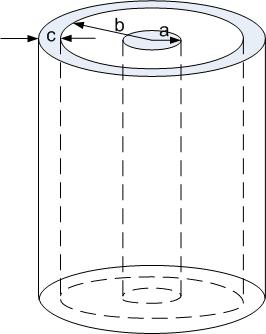
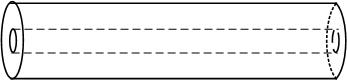
- (a)
- Coaxial Cable, Figure fig:qm/Coax
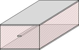
- (b)
- Microstrip, Figure fig:qm/MStrip
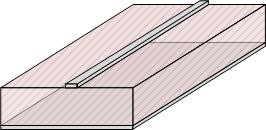
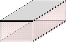
- (c)
- Stripline, Figure fig:qm/Strp
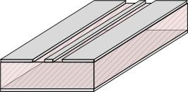
- (d)
- Coplanar Waveguide, Figure fig:qm/CPW
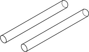
- (e)
- Two-wire line, Figure fig:qm/TwoWL
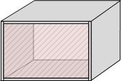
- (f)
- Parallel Plate Waveguide, Figure fig:qm/PPW
- (g)
- Rectangular Waveguide, Figure fig:qm/RecWG
- (h)
- Optical fiber, Figure fig:qm/OF
Propagation modes on a transmission line
Coax, two-wire line, transmission line support TEM waves. Waves on microstrip lines can be approximated as TEM up to the 30-40 GHz (unshielded), up to 140 GHz shielded.
- (a)
- Transversal Electro-Magnetic Field (TEM). Electric (E), and Magnetic (M) fields are entirely transversal to the direction of propagation
- (b)
- Transversal Electric field (TE), Transversal Magnetic Field (TM), M or E field is in the direction of propagation
Transmission lines we will discuss in this course carry TEM fields.