Again, we will look at a transmission line circuit in Figure fig:FVTRLine to find the input impedance on a transmission line.
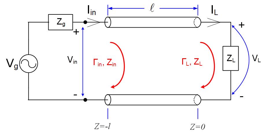
The equations for the voltage and current anywhere (any z) on a transmission line are
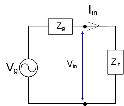
Using the equations from the previous section, we can replace the transmission line with its input impedance, Figure fig:FVTRLineEqCirc.
Forward voltage phasor as a function of load impedance
From Figure fig:FVTRLineEqCirc, we can find the input voltage on a transmission line using the voltage divider.
Using Equation eq:FVitlfin, we can also find the input voltage. The input voltage equation at the generator is:
Since these two equations represent the same input voltage we can make them equal.
Rearranging the equation, we find .
Forward voltage phasor as a function of input reflection coefficient
There is another way to find the input impedance as a function of the input reflection coefficient.
We write KVL for the circuit in Figure fig:FVTRLineEqCirc.
Using Equations eq:FVitlfin-eq:FVitlfin, we can also find the input voltage and current. Input voltage and current equation at the generator are:
Substituting these two equations in Equation eq:FVKVL we get
We can re-write this equation as follows.
Using that is the input reflection coefficient, and multiplying through with .
Rearranging the equation, we get
is the input reflection coefficient.
Special case - forward voltage when the generator and transmission-line impedance are equal
Because the generator’s impedance is equal to the transmission line impedance, we will use the second equation. When we see that the denominator simplifies into , and we can further simplify the fraction to get the final value of .