Reflection Coefficient and Impedance
Reflection coefficient and impedance are related through Equation eq:SCDereqnreflectioncoefficient. We can find an impedance that corresponds to the reflection coefficient, Equation eq:SCDereqnimpedancerc. Every point on the Smith Chart represents one reflection coefficient and one impedance .
All impedances on the Smith Chart are normalized to the transmission line impedance . The normalized impedance is denoted in Equation eq:SCDerNormImp with lowercase .
Derivation of Impedance and Admittance Circles on the Smith Chart
Impedance and reflection coefficient are complex numbers. The normalized impedance has a real and imaginary part , and the reflection coefficient can also be shown in Cartesian coordinates as . We can now substitute these equations into Equation eq:SCDerRealImag.
We can equate the real and imaginary parts on the left and right side of Equation eq:SCDerRealImag to get the equations of constant and .
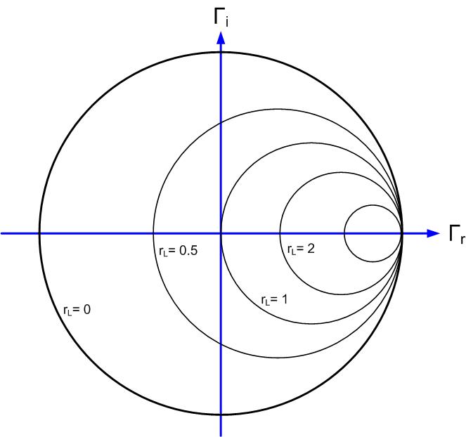
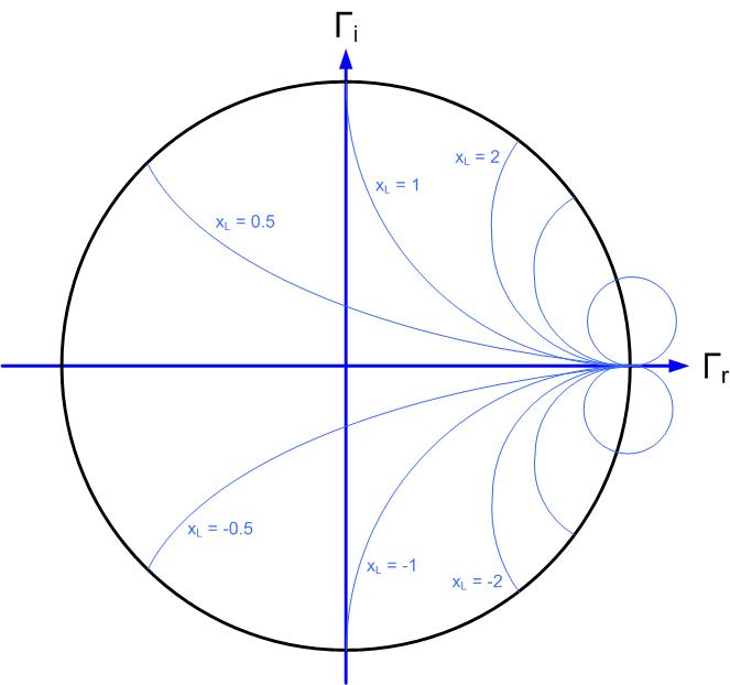
These are equations of a circle, with the constant resistance circle’s center at and radius ; and the constant reactance imaginary circle center at and radius of .
Figures fig:SCDerscresistance- fig:SCDerscreactance show circles on the Smith Chart that represent constant (normalized) reactances, and resistances.
Admittance circles can be similarly derived using the fact that and the Equation eq:SCDerNormImp