Simple impedance matching case
The simplest impedance matching case is when the real part of the load impedance is already equal to the transmission line impedance.
Let’s say that the load impedance is and needs to be matched to a line. This impedance represents a resistor of connected in series with a -reactance inductor. The reactance of is an inductor of inductance nH at 1GHz.
To make this impedance look like a impedance, we have to add an element with impedance, so that . Since impedance is negative, we know that we have to add a capacitor. Because we are adding two impedances, we know that they must be in series.
To look at this solution on the Smith Chart, we first normalize the impedance of the load , and then place it on the Smith Chart as shown in Figure fig:SimpleMatch as a red dot. To get to the center of the Smitch Chart, we use only the resistance/conductance circles. On these circles, centered on x-axis, only the reactance/susceptance of the impedance changes, and we don’t change the resistance. We only add capacitors or inductors in matching circuits, and so we keep constant the real part of the impedance or admittance. We see that the circle we have to use is the circle, where the real part of the load impedance is constant. To get to the center of the chart, where , we find the reactance to add to the load impedance. To make the final, matched impedance equal to one, we have to add impedance . Since this impedance is negative, it’s a capacitor. Another way to see that this is a capacitor is to notice that by adding this element, we are moving from the inductive (upper half) to capacitive part (lower part) of the Smith chart.
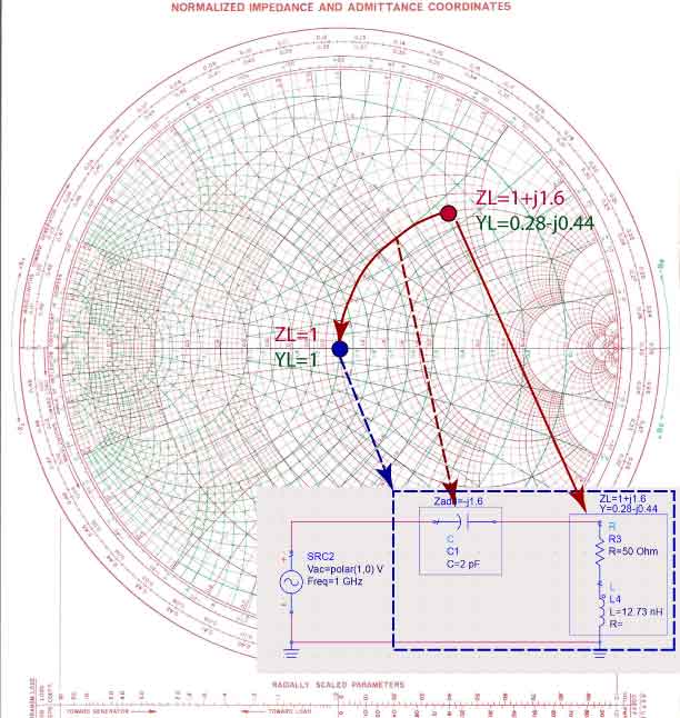
Finally, we have to find the capacitance of a . The added impedance is first multiplied by to re-normalize the impedance. The impedance of any capacitor is . To find the capacitance of this capacitor we set . From this equation, and keeping in mind that , we calculate that the capacitance is pF.