•  Get Help
    Contact my instructor
    Request help using Ximera Report bug to programmers
  • Me
    Profile Supervise Logout
  •  Sign In
    Sign In with Google Sign In with Twitter Sign In with GitHub
Warning

You are about to erase your work on this activity. Are you sure you want to do this?

Updated Version Available

There is an updated version of this activity. If you update to the most recent version of this activity, then your current progress on this activity will be erased. Regardless, your record of completion will remain. How would you like to proceed?

 Delete my work and update to the new version.
Mathematical Expression Editor

Sinusoidal signals

Basic Parameters of Sinusoidal Signals

Review of Sinusoidal Signals

Leading and Lagging Signals

Review of Sinusoidal Signals

eLi the iCe Man is CIVIL

Review of Sinusoidal Signals

Signal Delay on Transmission Lines

Review of Sinusoidal Signals

Engineering Design

The purpose of this section is to show one application of sinusoidal signals to engineering design.

Complex numbers

Review of Complex Numbers

This section aims to introduce two different ways we represent complex numbers: Cartesian coordinates, and Polar coordinates. We often use complex numbers in Cartesian coordinates when we discuss impedance or admittance. We often use complex numbers in polar coordinates to discuss magnitude and phase of voltages, currents, transfer functions, and Bode Plots. We can also represent sinusoidal signals with complex numbers with phasors. It is critically important that we understand this chapter.

Operations with Complex Numbers

The purpose of this section is to review arithmetic operations with complex numbers. We use complex numbers to describe circuits. When we solve circuits to find voltages, currents, and power, we often encounter addition, subtraction, multiplication, division, and the complex conjugate of complex numbers.

Euler’s Formula

The purpose of this section is to relate sinusoidal signals and complex numbers using Euler’s formula.

Phasors

Review of Phasors

Phasors are essential tool in circuit analysis, used in many applications. Phasors are a special case of superposition, that simplifies circuit analysis.

Kirchoff’s Laws

Phasors are essential tool in circuit analysis.

Example of circuit analysis with phasors

Phasors are essential tool in circuit analysis.

Waves on Transmission Lines

Types of Transmission Lines

Wave Equation

Visualization of waves on lossless transmission lines

Propagation constant and loss

Transmission Line Impedance

Reflection Coefficient

Input impedance of a transmission line

Forward voltage on a transmission line

Traveling and Standing Waves

Example Transmission Line Problem

Smith Chart

Smith Chart

Impedance and admittance circles on the Smith Chart

Impedance and Admittance on Smith Chart

Electrical Length

Input Reflection Coefficient and Impedance on Smith Chart

Impedance Matching

Power

Power Transfer on a transmission line

Simple impedance matching case

Mixed Impedance Matching

Transmission-line impedance matching

Lumped element impedance matching

Electrostatics

Electrostatic Force

Electrostatic Field

Electrostatic Potential

Electrostatic fields from distributed charges

Calculation of electric field using Gauss’s Law

Electrostatic Boundary Conditions

Capacitance

Method of images

Magnetostatics

Charged particles in static electric and magnetic fields

Force on Conductors

Force on Conductors

Biot-Savart’s Law

Ampere’s Law

Inductance

Changing electromagnetic fields

Faraday’s Law

Lenz’s Law

Transformers

Magnetic Coupling

Flying ring

Falling Magnet

Voltage droop

  1. electromagnetics
  2. Electromagnetics
  3. Waves on Transmission Lines
  4. Example Transmission Line Problem
  5. Milica Markovic

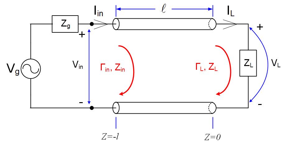
A transmitter operated at 20MHz, Vg=100V with internal impedance is connected to an antenna load through l=6.33m of the line. The line is a lossless , . The antenna impedance at 20MHz measures . Set the beginning of the z-axis at the load, as shown in Figure fig:TRLine.

(a)
What is the electrical length of the line?
(b)
What is the input impedance of the line ?
(c)
What is the forward going voltage at the load ?
(d)
Find the expression for forward voltage anywhere on the line.
(e)
Find the expression for reflected voltage anywhere on the line.
(f)
Find the total voltage anywhere on the line.
(g)
Find the expression for forward current anywhere on the line.
(h)
Find the expression for reflected current anywhere on the line.
(i)
Find the total current anywhere on the line.
(j)
Instead of the antenna, a load impedance is connected to this 50 Ohm line. How will that change the equations above?

PIC


Figure 1: Transmission Line connects generator and the load.

The equations for the voltage and current anywhere (any z) on a transmission line are

We are given phase constant , and we have to find the other unknowns: phasor of voltage at the load , and the reflection coefficient .

Since we know the load impedance , and the transmission-line impedance , we can find the reflection coefficient using Equation eq:reflcoe1.

To find the input impedance of the line, we use the equation

We can use one of the following two equations to find the forward going voltage at the load:

Because the generator’s impedance is equal to the transmission line impedance, we will use the second equation. When we see that the denominator simplifies into and we can further simplify the fraction to get the final value of . Since , the forward going voltage at the load is .

The equations of the voltage and current anywhere on the line are therefore

Suppose we replace the antenna with another load of impedance . In that case, the reflection coefficient from the load will be zero, and the reflected voltages will disappear, so the voltage and current will be equal to the forward-going voltage on the transmission line.

  • ← Previous
  • Next →
Courses
    Calculus OneCalculus TwoCalculus Three
About
    FAQDevelopment TeamWorkshopContact Us
Social
    Facebook Twitter Google Plus GitHub

Built at The Ohio State UniversityOSU with support from NSF Grant DUE-1245433, the Shuttleworth Foundation, the Department of Mathematics, and the Affordable Learning ExchangeALX.

© 2013–2023, The Ohio State University — Ximera team

100 Math Tower, 231 West 18th Avenue, Columbus OH, 43210–1174

Phone: (773) 809–5659 | Contact

If you have trouble accessing this page and need to request an alternate format, contact ximera@math.osu.edu.