The real part of the load impedance is rarely equal to the transmission-line impedance. In most cases, we have to transform the real part of the impedance as well.
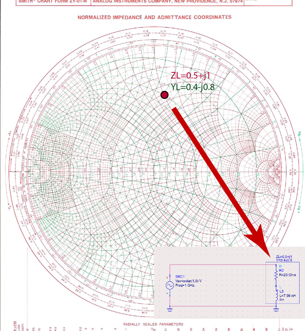
For example, load impedance represents a series connection of a resistor and a nH inductor at 1 GHz. To match impedance to the transmission-line impedance , we first normalize the load impedance to transmission-line impedance.
This impedance is shown in Figure fig:PointSC.
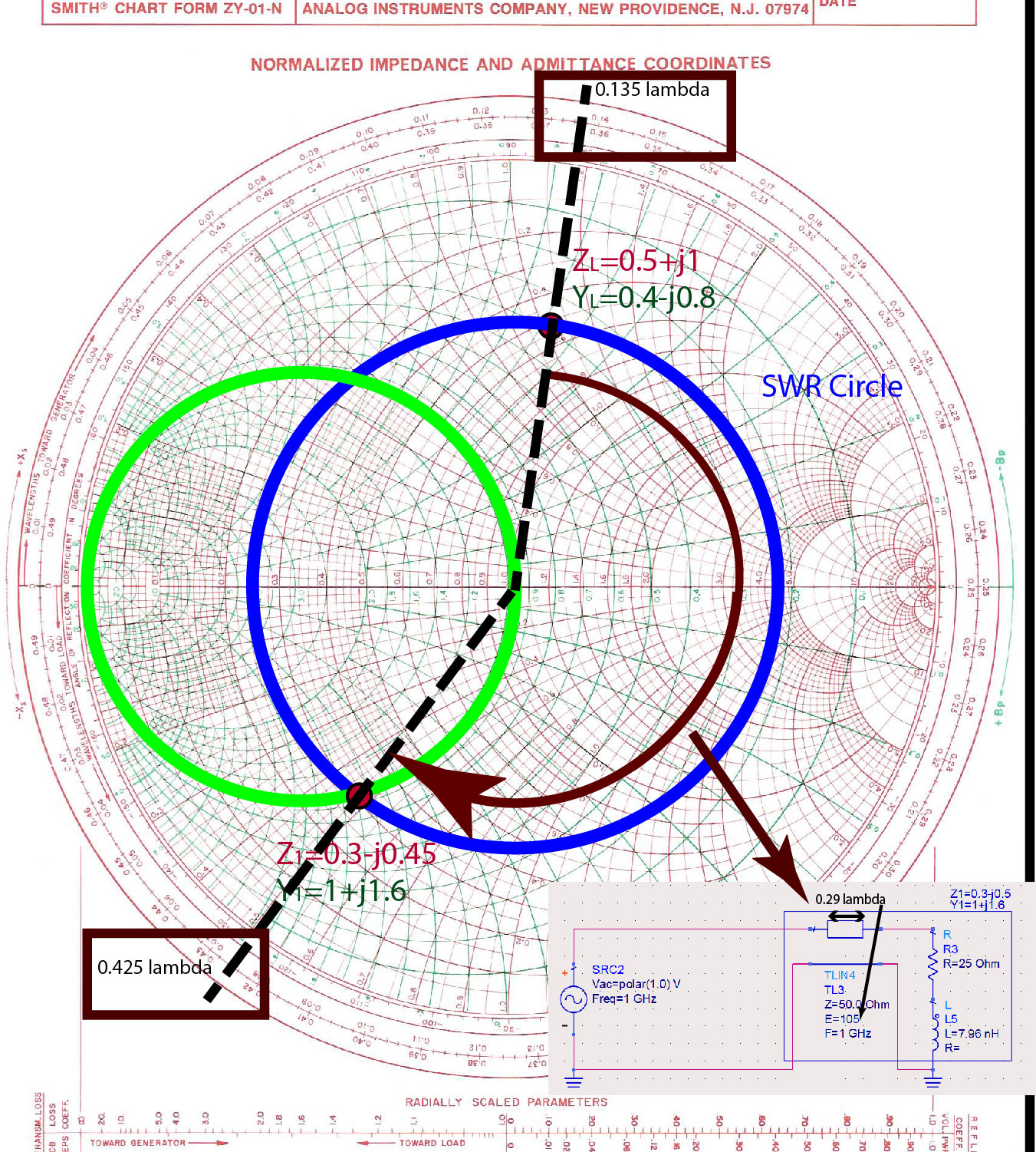
SWR circle
Then, we identify an SWR circle that this impedance is on, as shown in Figure fig:SWRfor25Ohm. The point where the SWR circle intersects the green circle is of interest because the real part of the input admittance is equal to one . This second point, where , will give us the length of the line that we have to add to the load impedance.
Length of the line that will transform the real part of load impedance
To find the length of the line that will transform the real part of to , we identify the position of the load impedance , and the input impedance at the Wavelengths Towards Generator (WTG) scale. The reason we picked impedance is because the real part of the admittance is equal to one . Load impedance is at , and the input impedance is at . The difference between these two positions gives us the length of the line . In electrical degrees, this length is approximately . The input admittance to the line is now .
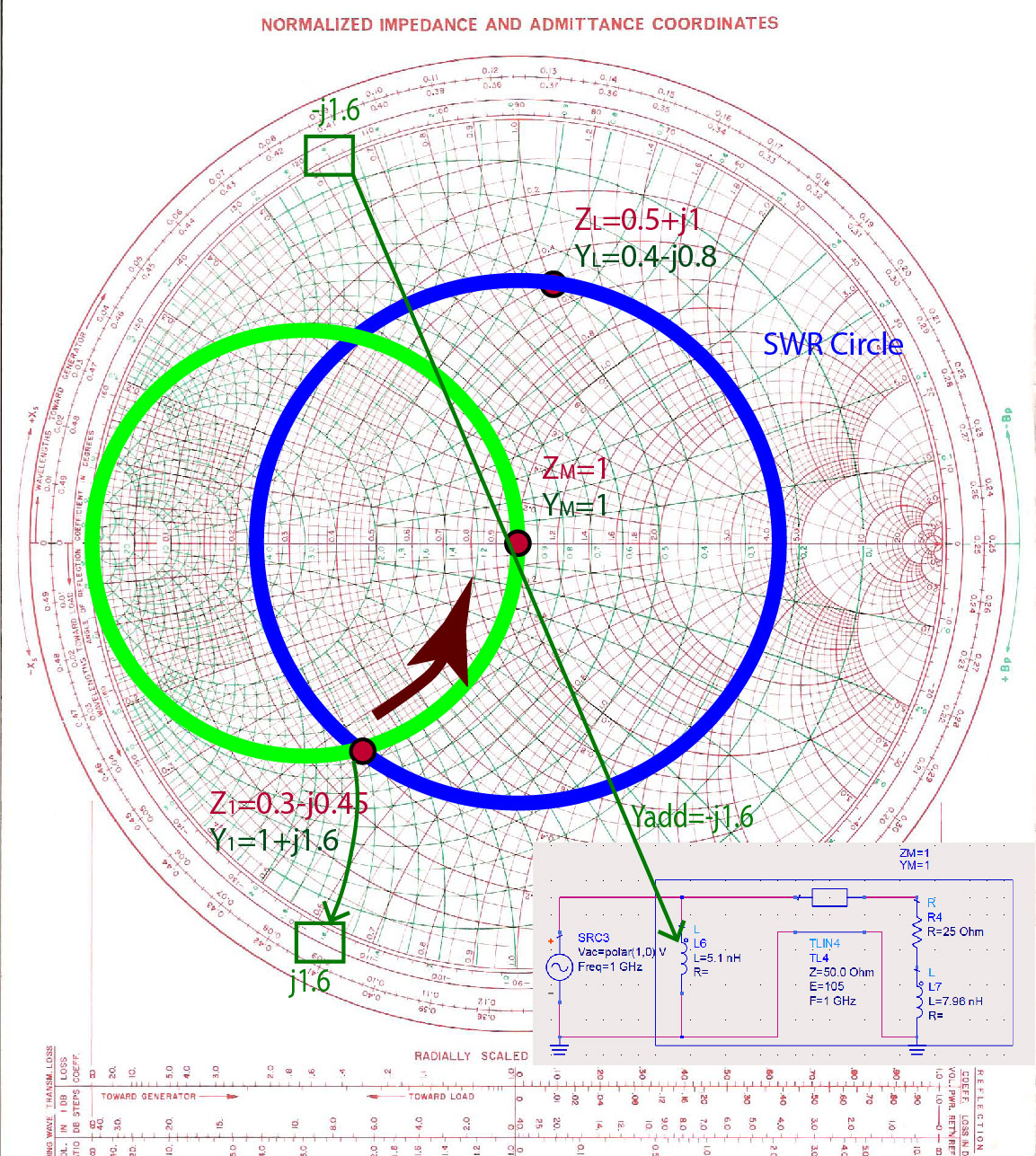
Adding a lumped-element to remove the susceptance
The final step is to add a susceptance that will remove the imaginary part of the input admittance . We see that to get the final admittance of , numerically, we have to add an admittance of . This represents an inductance. Since we are adding the two admittances , they have to be in parallel (as we know that when elements are in parallel, we add their admittances).
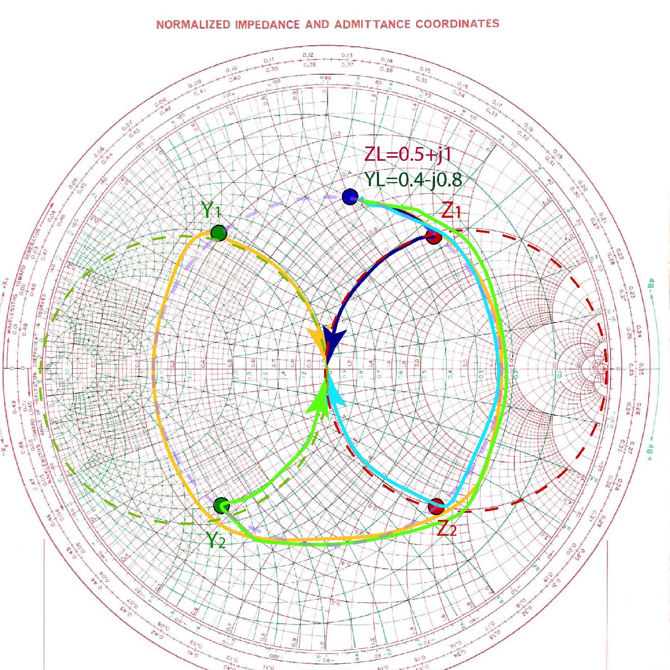
Other possible solutions
Graphically, there are several different mixed or transmission-line impedance matching circuits that we can make for a specific impedance. For example, for impedance , , there are four different circuits that we can make, as shown in Figure fig:MixedVariety. In this paragraph, we used the green path on the Smith Chart, with intermediate admittance .