Phasors are essential tool in circuit analysis.
The circuit in Figure RCcirc is a simple RC circuit. Equation eq-1 shows the KVL the time domain.
As we discussed in the previous section, we will be using the principle of superposition, and add another generator to the circuit, as shown in Figure RCcirc.
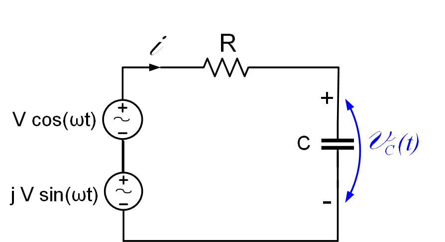
The generator we originally had in the circuit is now just the real part of the phasor expression shown in Equation eq2.
A common term in the previous equation is , and we can now drop , as long as we later remember to take only the real part of the expression for the voltage and current phasors to get the time domain expression. We can now write the equation as
Since this is a linear equation, we can easily solve it:
Converting the phasor back to the time domain
In general, if the phasor is , to find the time-domain signal, we first multiply the phasor with term, and then take the real part of it.