Force on a loop of current due to external magnetic field
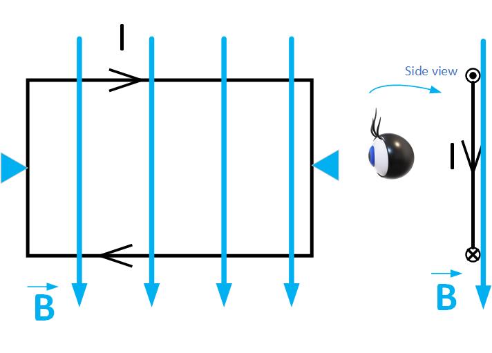
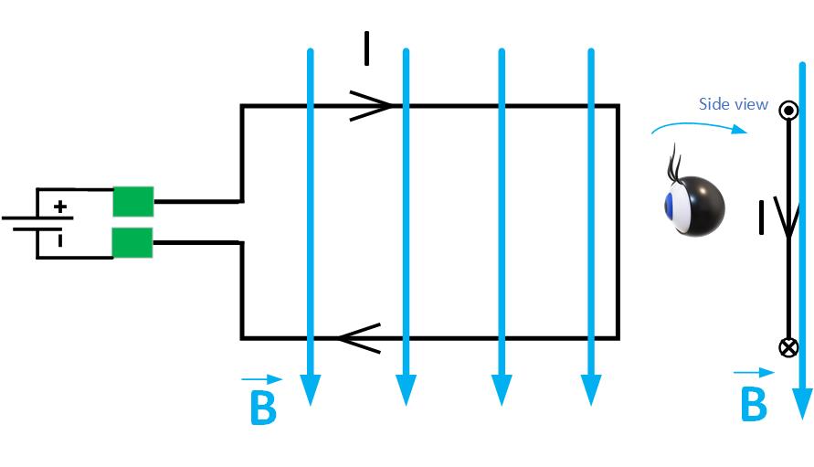
Figure fig:currentLoop shows a rectangular loop of wire carrying current I in the presence of an external magnetic field B. The loop is fixed along the horizontal pivot axis and can rotate only clockwise or counterclockwise. If we observe the loop from the left, we see the current flows toward us on top, indicated by a circle with a dot on the side view. The current flows away from us on the bottom, indicated by the circle with an x.
Force on a conductor of length due to an external magnetic field is
Vector is in the direction of the current.
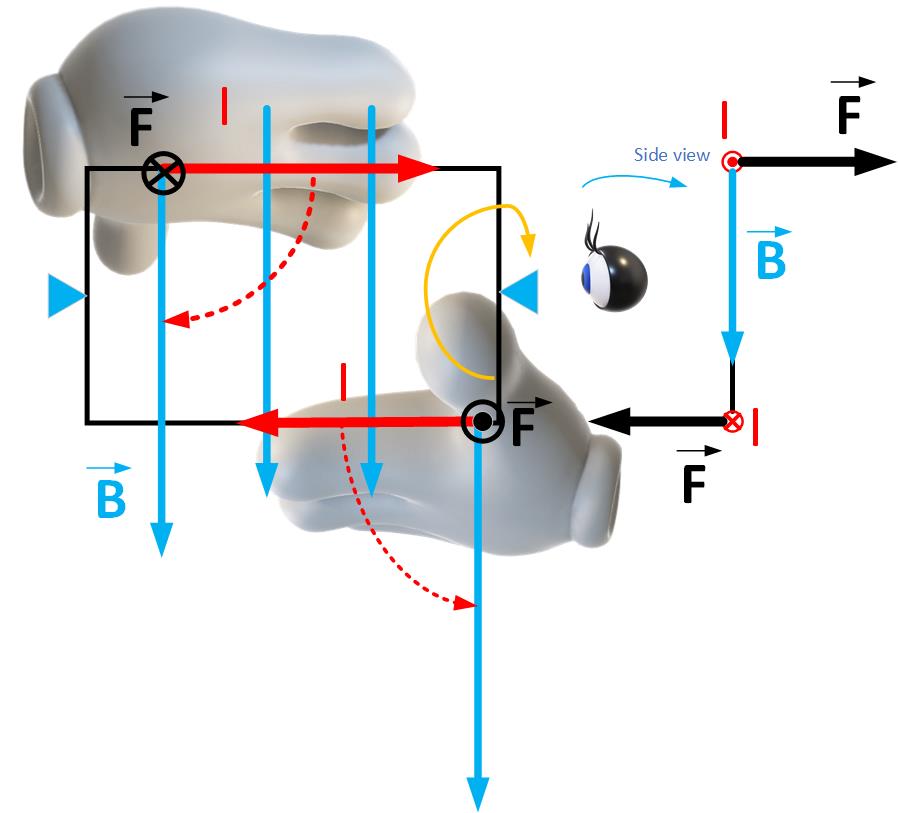
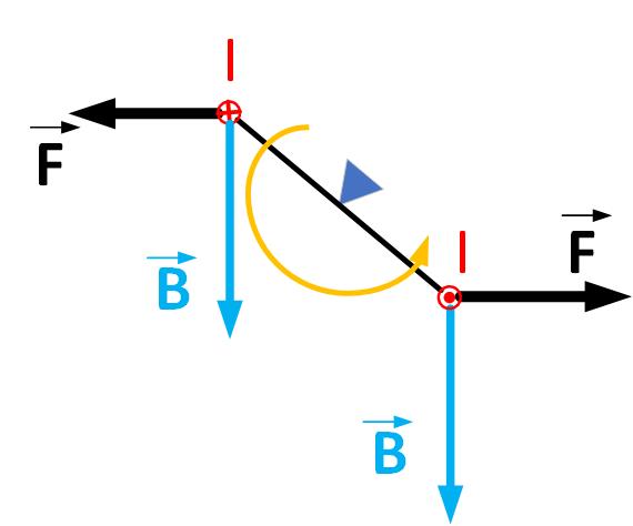
Which way will the loop turn? We use the right-hand rule to determine the direction of rotation, as shown in Figure fig:currentLoopTorque. Imagine that the current is in the palm of your right hand. Orient the palm so that you can sweep your fingers toward the magnetic field vector. The thumb shows the direction of the force. Which way will the loop rotate? Think of pushing the top of the loop into the page in the force’s direction and pulling the bottom of the loop towards you. The loop will rotate clockwise in the direction of the orange arrow.
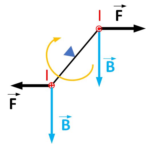
When the loop moves from the original position, the magnetic force will continue to rotate the loop, as shown in Figure fig:currentLoopTorque1.
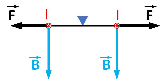
When the loop surface is perpendicular to the vector of the magnetic field, as shown in Figure fig:currentLoopTorque2, the magnetic force becomes zero. We may think that the loop will stop moving because the force becomes zero. However, because the loop has mass, the loop will continue rotating because of the inertia.
The magnetic forces will start working to move the loop back to this stable point, as shown in Figure fig:currentLoopTorque3. The loop will then move back and forth until it stops.
If we want continuous rotation, we need to change the current direction at this stable point or the magnetic field. That brings us to DC motors.
DC Motor
DC motors convert electrical energy to mechanical energy. A battery supplies DC voltage to a current loop that produces a current in the loop. DC motors have a special split-ring piece that connects the loop to a voltage source called a commutator. When the magnetic field rotates the loop to the stable position, as we discussed in the previous section, the commutator’s gap stops the current in the same direction for a moment, then connects the opposite pole of the battery, making the current go in the opposite direction. The orientation of the current and the magnetic field produce force in such a direction to continue the loop rotation.
To see the simulation of a DC motor, take a look at the following simulation