Phasors are essential tool in circuit analysis.
- (a)
- adopt cosine reference for generator voltage or current.
- (b)
- replace all impedances with their phasor expressions,
- (c)
- write KVL and KCL or use other Network Analysis techniques.
- (d)
- find the phasor expression for the required current or voltage.
- (e)
- calculate phasors
- (f)
- sketch the phasor diagram
- (g)
- multiply the phasor with
- (h)
- find the real part of the above expression to get the current in the time domain.
It is customary in Electrical Engineering to use for our time-domain signal, and we call these phasors ”cosine reference phasors.” If the generator in a circuit is , we first have to convert the sin function to a cosine. To do that, subtract from the phase of the sinusoid, because .
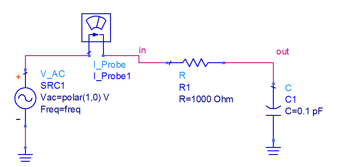
A series RC circuit shown in Figure RCcircADS. The circuit is driven with a frequency of 1 GHz , and R=1k, C= F.
- (a)
- Identify magnitude, phase, and time-delay of the source voltage.
- (b)
- Calculate magnitude, phase, and time-delay of the voltage across the resistor.
- (c)
- Calculate magnitude, phase, and time-delay of the voltage across the capacitor.
- (d)
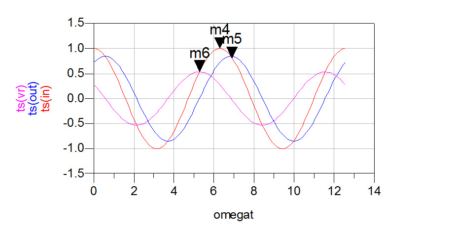
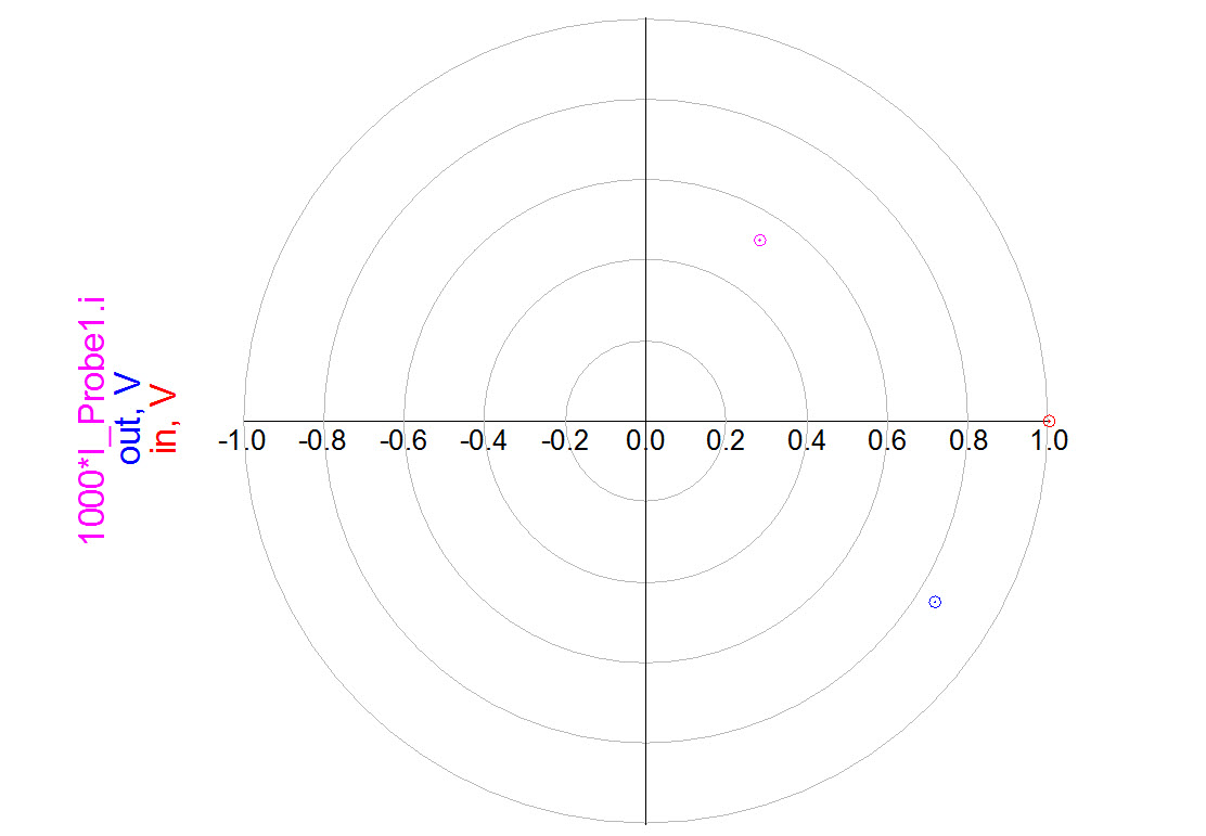
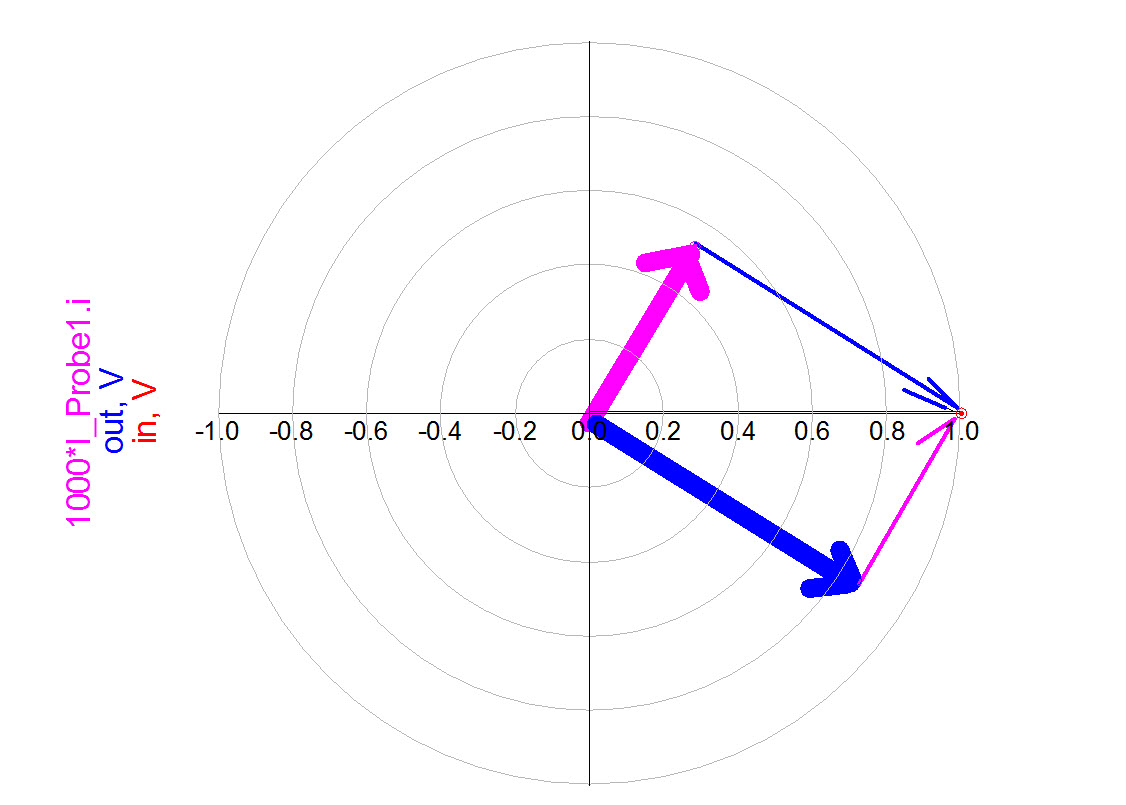
- The simulated voltage magnitude across the resistor is about 0.5V, and the simulated voltage across the capacitor is about 0.85V. If we use KVL . Why? Look at Figure f112 to answer this question.
- (e)
- Sketch the phasor diagram of voltages in the circuit.
Solving for voltages and currents in the circuit.
- (a)
- The generator is already given in terms of the cosine function. The phasor of this voltage is
- (b)
- replace all impedances with their phasor expressions. R is not changed, and the impedance of a capacitor is .
- (c)
- Use Kirchoff’s Voltage law
- (d)
- find the phasor expression for the required current or voltage.
- (e)
- calculate the currents and voltages from the above expressions
- (f)
- When you calculate the magnitudes and phases of the voltages in the RC circuit, draw three complex numbers to represent all three vectors’ magnitude and phases, as in Figure PP. The three points denote the three position-vectors, as shown in Figure f112. We must use vector addition to add the voltages on the resistor and capacitor to obtain the generator’s voltage. The magnitudes of voltages do not add simply as real numbers, because the voltages have different phases. Complex numbers magnitudes are added only if their phases are the same; in other words, if the phasors point in the same direction, as is the case for purely resistive circuits. However, if we use vector addition (or complex number addition) in any circuit, we will get that the vectors of voltages add up to the source voltage.
- (g)
- multiply the phasor with
- (h)
- find the real part of the above expression to get the current in the time domain.
Time domain signals are shown in Figure SSangle.
To find time-delay for each signal, we will use the equation . Since angles above are in degrees, we need to convert degrees to radians. . Time-delays are as follows:


