Ideal Transformer
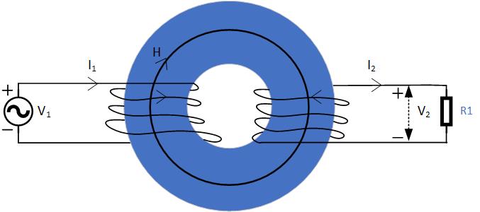
Transformers consist of two coils of wire on a ferromagnetic core, as shown in Figure fig:Transformer. The left coil with an AC generator is called a primary, and the right coil with the resistor is called a secondary. There is no voltage source in the secondary. Transformers are used in many applications, some of which are to electrically decouple circuits, match impedances, and increase or decrease the primary voltage. In an ideal transformer, it is assumed that the total flux produced by the primary will be circulating through the core, and therefore the secondary as well. The induced voltage on the primary and secondary are
If we divide these equations, the ratio of the emf and voltages is
Since we are assuming an ideal transformer with no loss, the input power generated by the primary will be equal to the output power delivered to the secondary , we can replace the ratio of voltages in the equation above with currents to get
The more turns we have on the secondary, the higher the voltage be. Watch the following video to see a demonstration of a transformer.
