, ,
In an electrical network it is often necessary to find the current in amperes () flowing in various parts of the network. These networks usually contain resistors that retard the current. Resistance is measured in ohms (). The current is increased at various points by voltage sources (for example, a battery). The voltage of these sources is measured in volts (V). We use the following symbols to represent resistors and voltage sources:
We assume these voltage sources have no resistance. The flow of current is governed by the following principles.
When applying the Circuit Rule, select a direction (clockwise or counterclockwise) around the closed circuit and then consider all voltages and currents positive when in this direction and negative when in the opposite direction. Here is an example.
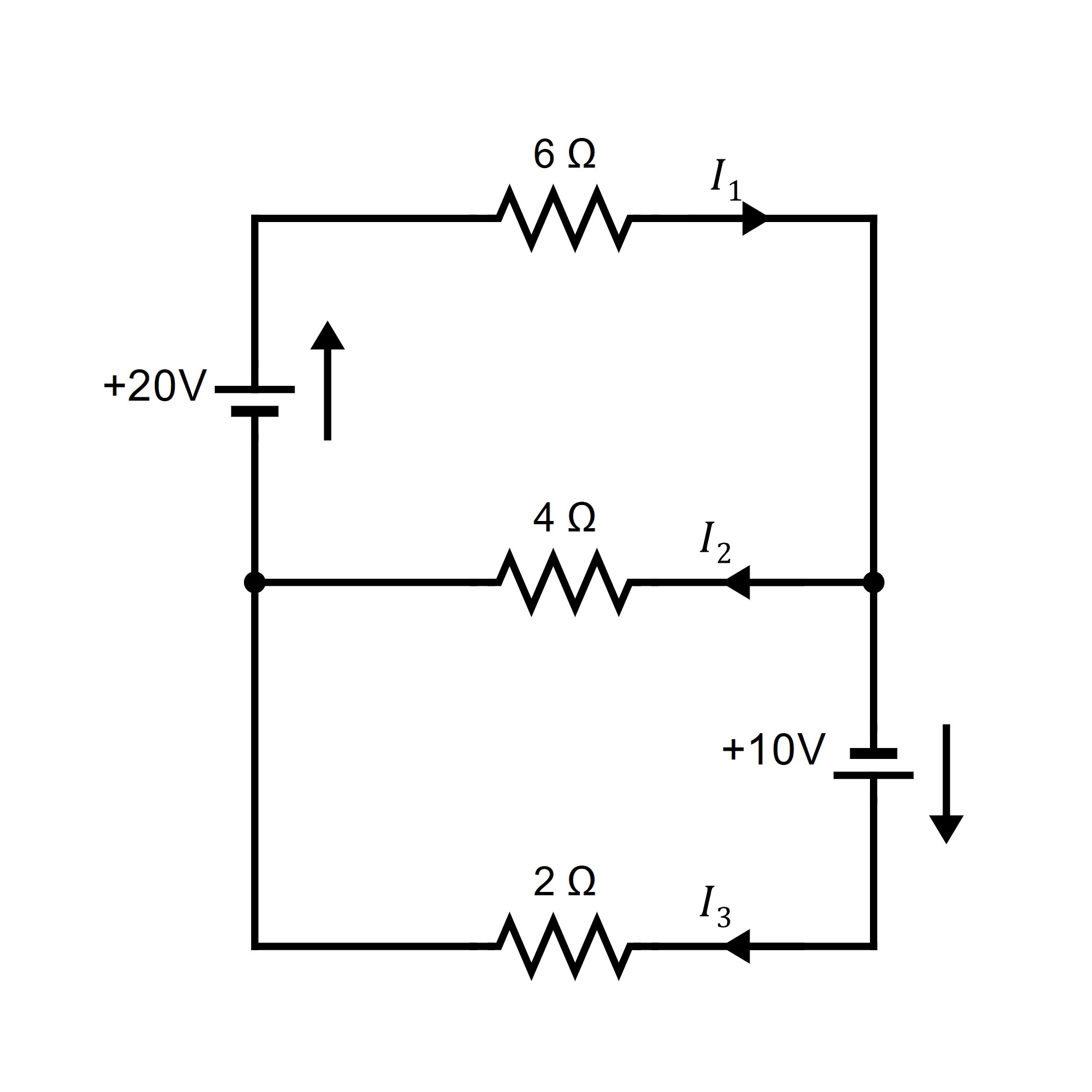
Find the various currents in the circuit shown.

Note that these equations are not independent (in fact, the third is an easy consequence of the other three).
Next, the circuit rule insists that the sum of the voltage increases (due to the sources) around a closed circuit must equal the sum of the voltage drops (due to resistances). By Ohm’s law, the voltage loss across a resistance (in the direction of the current ) is . Going counterclockwise around three closed circuits yields
Hence, disregarding the redundant equation obtained at junction , we have six equations in the six unknowns . The solution is
The fact that is negative means, of course, that this current is in the opposite direction, with a magnitude of amperes.
Problems prob:circuit1-prob:circuit6
Find the currents in the curcuits.
This application was adapted from Section 1.5 of Keith Nicholson’s Linear Algebra with Applications. (CC-BY-NC-SA)
W. Keith Nicholson, Linear Algebra with Applications, Lyryx 2018, Open Edition, p. 29
Circuit Diagrams were made using https://www.circuit-diagram.org/
2024-09-26 22:11:26